The unit I modeled is coming out at around £30-40 to have 3D printed and even more to have printed in ABS.
That does seem way over the top. The case I've put together weighs in at 75g, and at the price I'm paying for PLA and ABS (£18 a kilo - cheaper filaments are available) it that comes in at £1.35 a pop, plus whatever electricity the printer uses in the process. Obviously, I've probably printed off a kilo or so in prototyping, but once you've got a workable design the cost of the 3D printed item is nowhere near £30-£40.
For those that are interested, I've put the OpenSCAD source files and STLs for the case here:
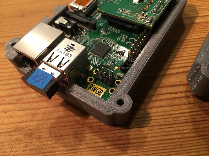
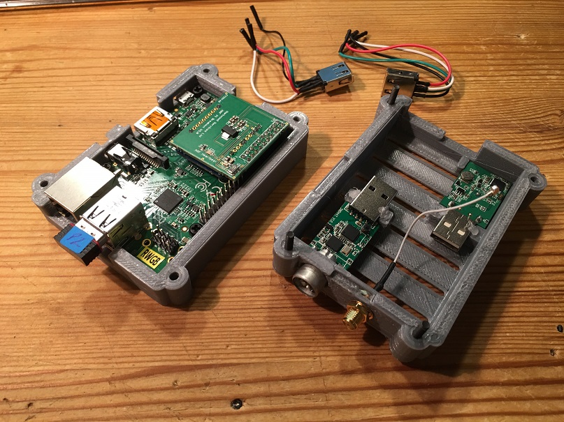
https://github.com/rollingcircle/packapawBasically, the idea was to swap out one of the USB ports in the Pi with a header, remove the cases from the DVB and GPS dongles, and mount them inside the case wired directly to the headers.
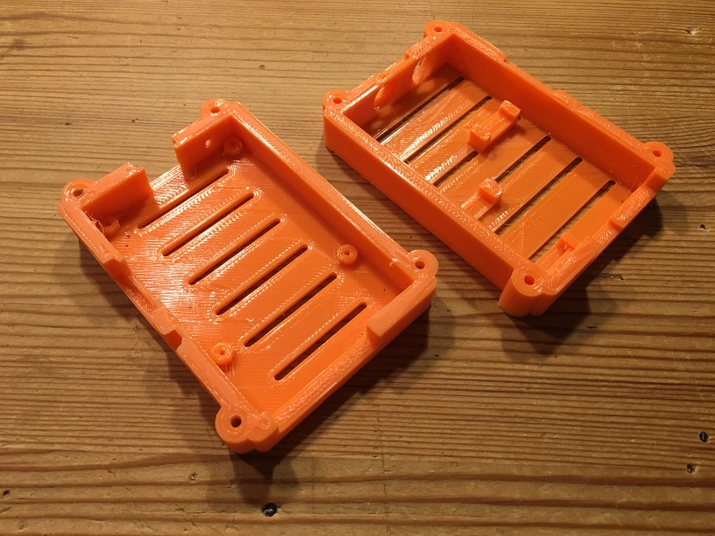
The base is pretty much a generic B+ design, with the second USB port blocked off...
https://github.com/rollingcircle/packapaw/blob/master/packapaw_base.stl..the lid has voids for the antennas, and mounting brackets for the two modules...
https://github.com/rollingcircle/packapaw/blob/master/packapaw_top.stlThe DVB dongle mount clamps at either end, leaving the board in free air for cooling - I haven't really had time for much testing, but running it on the bench for an hour or so the lid over the dongle only became faintly warm.
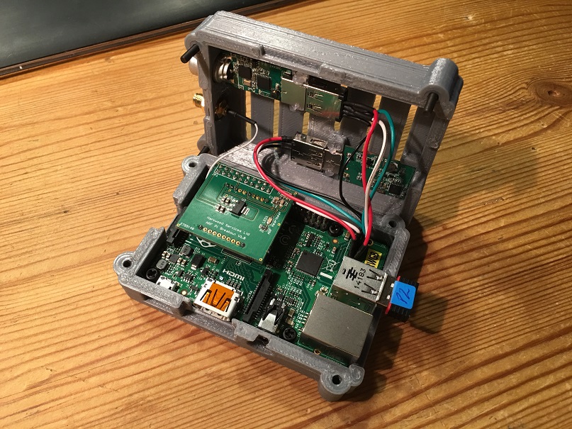
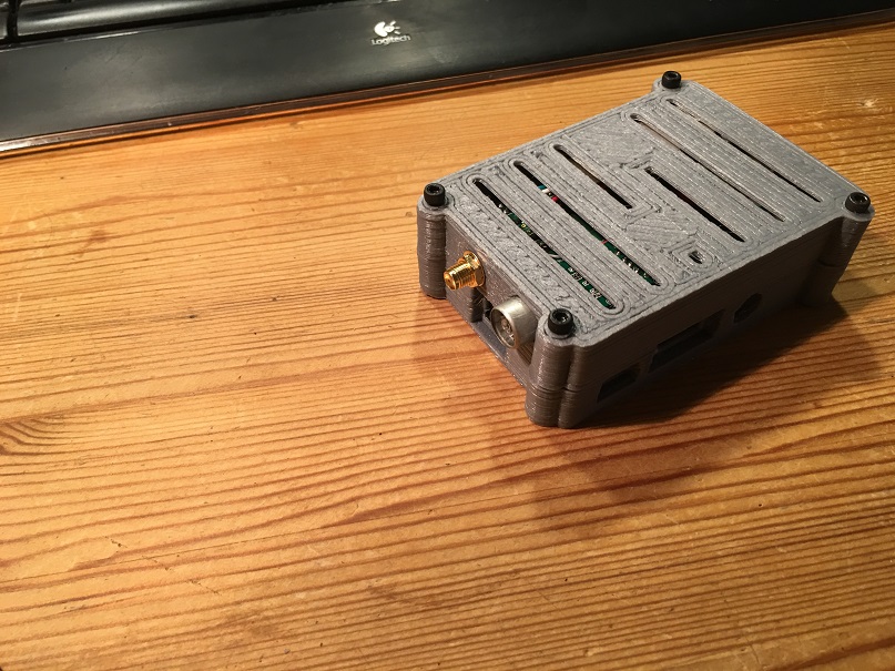
I did notice the GPS was rather less sensitive in there with the ARF powered up, but being next to the ARF is probably a GPS module's equivalent of sticking your head in a speaker stack at a Motorhead concert.
The OpenSCAD source and the STLs are up on GitHub under the Creative Commons license, so you can do what you want with them.
The case needs a bit more work - the tapered capture in the bolt holes is a bit abrupt, so currently difficult to screw the halves together tightly.
So, if you needed another reason to get yourself a 3D printer for Christmas, there you go!


