Show Posts

You can view here all posts made by this member. Note that you can only see posts made in areas to which you currently have access.


Messages - rv12uk

Pages: [1] 2
1
General Discussion / Re: Mini Traffic Aware (MTA)
« on: February 15, 2018, 11:47:54 pm »
I thought I would have a go at the start of a video series on making the MTA if anyone is interested.

Due to the time these take, I may not finish the complete series off if there isn't enough interest in them.


2
Technical Support / Re: Raspberry Pi Monitor
« on: February 12, 2018, 12:24:07 am »
I have started a new thread on the MTA display thing I have been working on to avoid clogging up other posts.

http://forum.pilotaware.com/index.php/topic,1179.msg13916.html

3
General Discussion / Mini Traffic Aware (MTA)
« on: February 12, 2018, 12:19:58 am »
I've had a few inquiries recently about the display I have been playing around with.
I don't currently have a single place I'm documenting it where I can get feedback (my blog site is more a one way medium) so thought it might be useful to put a post on here (if that is ok with the moderators).


What is the MTA
The unit is designed to be a small and light display to show the nearest target that PAW is currently tracking. I didn't start out to make this as I was just playing around and trying to learn some Arduino and electronics and this is what I ended up making.

The two main uses I see for this would be
  • Have a small unit in your eyeline to alert you to the nearest target (without needing to look down at a tablet on the passenger seat).
  • Use in a small aircraft or weight-shifter where it could be worn on the wrist or mounted with little space needed.
The display connects to a PAW unit in the same way as other devices (wifi)

Current Status of the project
Currently the unit could be considered in alfa stage whereby I have something cobbled together that kind of works but I don't know if it works correctly. I haven't got the unit in the air yet but it has been tested on a PAW in the house and receives and displays the targets ok.
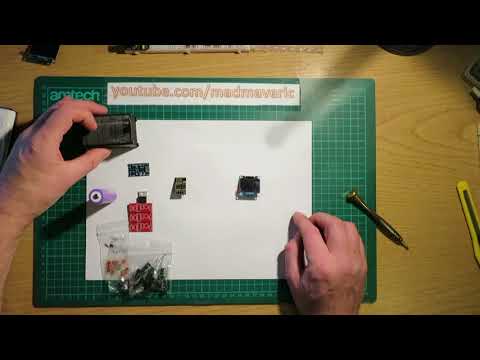
The current status can be seen in this video.


Background and technical stuff
This is mostly taken from my blog site at 
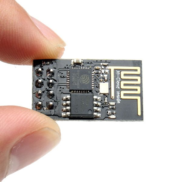
https://rv12uk.blogspot.co.uk/2017/12/105-mta-mini-traffic-aware.html
The brains of the device
The idea came from a decision I made to try my hand at some electronics. I was playing around with arduinos and something called an ESP8266-01 board (which has been also called the 'Internet of things device' due to it's abilities). The '-01' is the smallest form factor of these boards. From this I wanted to make something rather than just playing around so decided to see if I could get it to receive/process and display the PAW data.
At first I was going to add a large screen but as this is such a small device I decided to see how small and light I could make it.
The ESP8266-01 is a tiny board that has wifi, memory, a processor and runs at very low power.


Combine this with a power supply+screen and you have all the components needed to get something working.
The first attempts were simply done on a breadboard and the unit is programmed using the standard Arduino IDE.
The code can be broken down into three distinct tasks.
PAW connection
The Wifi components are pretty much used as is from the Arduino supplied ESP8266-01 libraries (plenty of stuff on the web about them). It just needs to connect to the PAW device and then read the stream of data from it.
Processing the data
The processing part is all hand written and parses the incoming data and chooses a target. This involves working out the target range or priority to decide if we want to display it as well as expiring the targets
Displaying the data
The ESP8266-01 model chosen only has two output pins so the only option was for I2C connection to the display. Larger modules can be used that provide more output pins but I wanted to keep this as small as possible. I ended up writing my own graphics library for this as I needed the minimum code and the supplied ones were all bloated with features I didn't need or want (and probably wouldn't fit in the small amount of memory available once the processing code was added). This did take a while to get right and all the images needed creating as they are all stored as HEX dumps. Fun times.
The graphics display has to interpret the data from the processed track to decide what to display as well as containing text display options, there are no 'print' style functions here for text. It is all done by uploading the HEX array to an array of screen memory using the I2C protocol.
Other code
As well as the main code above there is a lot of supplemental code. This is stuff for logging, timeouts, reconnecting of the wifi etc.

The video below shows the early breadboard testing.


Once the breadboard version was up to a level where I could look at getting it into a case I decided to see if I could get it to work with the minimal of items (removing all the programming hardware). The first test was just using two pencil batteries and an early first print of the case.


Power supply
The next step was to figure out a way to power it. This would ideally be a lipo as I didn't want to have wires going to the device restricting where it could be used. I'm currently using a small RC helicopter battery as it seems like it should provide the 1+hr minimum duration I decided on (should be more but testing is needed to find out how long it can run for)
Regulating this supply was one of the biggest headaches to solve.
The EPS8266 module takes 3.3v and the lipos have voltages anywhere from 2.5v to 4.3v depending on the charge state.
I needed a regulator that could run it from a single cell lipo, but I couldn't find anything that would work how I wanted at the time. Most would sap too much power (reducing the amount of battery capacity available)
I ended up designing a circuit board using the DipTrace software and getting it made by https://www.elecrow.com/. I used TV1262-3.3VAB Voltage regulators from Farnell to regulate the power. A simple circuit with a couple of capacitors were all that was needed.
I added a small micro USB lipo charger off ebay so that part was easy.
Case
Originally I thought I would be able to just buy a case for the components but after a lot of searching I couldn't find one good enough. Most would be too large for the job. As I had a 3D printer sat in the corner of the room I decided to have a go at making one. I had only used it for simply items before so this was quite a big job.
I designed the case using FreeCAD and ended up making the internals contain brackets for the components. It still needs some tweaking but the early versions seemed to work ok.

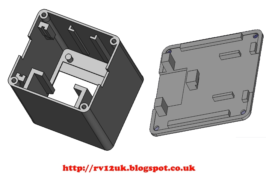
It is a bit of a squeeze getting all the components in there without pulling wires off, some of the component boards needed slight modifications to get them to fit but with a bit of persuasion (swearing) they all got in there.

I will try and keep the post updated when things change but it could be a few months between updates.

4
Technical Support / Re: Raspberry Pi Monitor
« on: February 11, 2018, 10:29:43 pm »
The light weight and small size is something I was aiming for, once I had decided to make something real out of the initial electrons project.

Once I have the aircraft flying (it's currently in the test flying stage) and have the PAW installed I will look at continuing the testing/development.

I'm currently pleased with the weight and size of the unit (it could be used on a wrist strap easily for weight-shifts etc), I also have some other ideas for a small display that I might get round to eventually.

A couple of people have asked if I plan on providing either kits or the parts/software/CAD files/instructions so they can have a play at making their own, I might do eventually but for now I'm still working on it.

The cost of parts for the whole lot is probably around £20, but to create a second one at the moment would take a few days work (most of that would be the 3d printing) so I need to work on that. A purchased case would be ideal but that would almost certainly make it larger.

I was planning on doing a video (possibly a couple) on how to make one but since youtube took away my 'YouTube Partner' status I felt a bit hard done by, and stopped doing videos for now.
I currently have 1460 hrs watched time on 232 videos I have up there with a total ad revenue of £52. This doesn't get payed out until I hit £60 (would be my first payout) and in 9 days time I lose my partner status so I have no chance of hitting that target.
The money is nothing compared to the time it takes to make the videos, but the principle of them just removing me with a months notice has pissed me of a bit. I might get over it or find another hosting site but for now I don't plan on putting any more videos on there.

As for doing kits and stuff I will wait and see what the end product ends up like (might be unusable) and see if anyone is interested. Then I can see if it is going to be worth it and decide the best way to do it. At the moment there isn't much to provide, the code isn't up to much and needs a fair bit of work to be reliable, I don't even know if is it showing the best target etc. Plus it only works with one type of screen at a time and you don't know which one you get until it arrives.
The CAD files I have only work with the current items I'm using and some of these are custom circuit boards I had made so that is also no use to anyone unless I supplied the boards I'm using (which are probably going to change).

If it turns out to work ok in real world use and someone wants one, I can look at making it simpler while keeping the cheap/small/light parameters and provide others with one (either by providing the software/CAD, parts kits or maybe making up some units). I doubt there would be many people interested in using one, most will just use a tablet.

If you might be interested let me know and also if you just want instructions on how to make one, code and CAD, parts, or a fully built one. It might never happen but if it does it would be good to know what to aim for when I start looking at it again.

5
Technical Support / Re: Raspberry Pi Monitor
« on: December 18, 2017, 10:22:15 pm »
It shows range as the crow flies, when closer than 1km but the data in the previous video wasn't close enough. When under 1km a bar appears on the left side increasing in size until the distance is 0 (full bar).
I could change it to show horizontal and vertical bars to give a better feeling of where the target is. At the moment a small bar (1km away) could mean it is over head 1km above or the same height but 1km away horizontally. Not great but ok for now.

I don't know yet if all targets are captured or how it will deal with targets where there's no position data, I might need to do some more processing of the messages (it's possibly I'm not capturing all the ones needed at the moment, it is still in pre-beta stage :D). I have just programmed it to look at the PFLAA and PFLAU targets and work out the closes from the x,y,z distances. If it looks like it will work in the real word then I will have a closer look at the data being processed.

This was more a hobby/fun project for myself. It could be useful for small aircraft though where the PAW is stuffed in the back somewhere and there isn't much space for a display. You could basically put it on a watchstrap with the size and weight of it ;D

This video show the display and what the icons mean.


This one shows the ESP8266 and screen inside the early case (minus the latest one with lipo, charger and power regulator at this point). Just two items and a power source needed.


Using this method it should be scalable up to a larger screen/radar using the later versions of the modules, the size and weight would be constrained on the screen and battery as the modules are so small.

6
Technical Support / Re: Raspberry Pi Monitor
« on: December 18, 2017, 07:55:48 pm »
I've been working on a standalone display for a while (actually not working on it as it's been on pause while waiting for a PAW unit). I have just received my PAW this weekend and have been back looking at it today (dusting off the bits for real).

My remit was to make it as small, cheap and light as possible while still providing a functional unit (it was more of a fun exercise in electronics than anything else) and it is only meant to point to the nearest target, not to display a 'radar' of targets.

I ended up using a small display with a ESP8266 programmable wifi module to receive, process and display the data. In my case it handles the processing and displaying ok.

This is using the smallest/cheapest ESP8266 you can get (<£2.00) instead of a Pi, the newer ones are faster with more memory I believe so they might be better for a more graphical intensive program as you are looking at.

I'm just mentioning it in case you want something a bit less bulky than a PI.

I did an updated video for it today (older videos of the 'bit's can be found under 'MTA') to show the display working with the live PAW unit.

7
Technical Support / Re: Is there a dummy PAW program?
« on: April 27, 2017, 11:50:55 pm »
Cockpit readability is always an issue with electronic screens. The problem is getting a good contrast without glare.

This little screen has a matt finish and is quite bright (when run at full power), the more I play with it the better it seems like it might work in the real world. A simply black and white display that is small enough to be level in the eye line wasn't originally in the plan but it looks more like it might be a good way to go.

I have started on a designing a case for this screen (can't finish it until I decide on the power source) but it gives an idea of the overall size of the unit that I am now affectionately calling the MTA (mini traffic aware) as I needed a name for the thing :D
https://youtu.be/iPTKurYYtq0


I keep coming back to play with this thing even though I should be doing other stuff :P


8
Technical Support / Re: Is there a dummy PAW program?
« on: April 25, 2017, 01:30:10 am »
Thanks, It has changed a bit in my head as I have played around with it.

Originally I was considering creating an instrument to fit alongside normal ones but as the kit is really light I thought it might be better to have it Velcro'd somewhere in sight (maybe even the top of the instrument panel if it was small enough).

I have seen these things running on two AA batteries but I would probably go for an inbuilt lipo plus usb charge socket (or a replaceable batteries), coincidentally, I was looking at lipo charging circuits last night (great minds and all that :D).

It is still a way off from being something usable at the moment (I'd really need to test it with a real PAW unit along side something like SD to make sure it was getting things right). Next step is to create an enclosure to see if I can get a portable unit to try out when the time comes (hopefully later this year at the rate I'm going with the kit).

I considered the multiple target option and have been thinking of ways it could be implemented, maybe using an altimeter/clock system (smaller hands for the other targets) would work. This version I want to keep as simple as possible (no buttons/config just turn the power on and leave it do it's thing). The other ones I have in mind would use buttons/touch screen for different options/settings but they are in the future at the moment.

I have also reconsidered the screen i'm using, I would love to know if it is viable in an aircraft (brightness wise) as something this small (1.3" screen) would be easy to fit on a dash without blocking any forward view, so it might be possible to use the setup I have already (it might be big enough if it were placed on top of the existing panel in direct line of sight).

This all assumes I progress with it, until I have a valid data source it isn't worth going too far with it at the moment, a valid PAW source may just swamp the unit and make it useless. Also by the time I get something for the data later this year (when I have finished building my kit with a SkyView display) I may decide the SV is good enough.

I thought the testing was useful enough to share for other to see/get ideas from. It started as a way for me to learn electronics so even if I don't plan on using the finished item myself it would be worth continuing for the learning experience, and it keeps the inventor in me happy (plus the end product might be useful to someone else).


9
Technical Support / Re: Is there a dummy PAW program?
« on: April 22, 2017, 02:17:19 pm »
Due to a weeks delay in my next kit turning up I had another play around with this idea.

I created a small set of PFLAA data for a single track, mixed in some GPS and PFLAU data and created a RPI program to push it out of port 2000 (very buggy bit of code but when it isn't crashing it seems to work :o).

I updated the firmware to calculate the distance to every target it sees and then display the closest (as the crow flies) target.

Not having access to real PAW data I don't know how fast it would come in or if I have the protocol exactly right but the chip seems to be able to handle the calculations needed for the target/graphics display maths ok. With modern chip speeds it has been a while since I have had to code for size/performance so I'm a bit rusty and I'm sure more can be done if needed.

For now this project will be going on the back burner (i.e. slow progress) but at least I have something to tinker with when I get time.

I did another video to show the latest mock up with with kind of display I'm thinking would be useful (needs more graphics work but it gives the general idea).
https://youtu.be/WD-4_aBVQEI

The original idea was to build a 2 1/4" instrument but now I'm thinking of a small cigarette packet sized box (or the minimum size for the 2xAA batteries needed if I stick with the current screen) and using a strip of velcro to mount it.

10
Technical Support / Re: Is there a dummy PAW program?
« on: April 12, 2017, 11:55:05 pm »
It can be tricky to get working as there's lots of partial info out there and different ways of doing things with it, so every person seems to use different firmware/API packages.
It does appear to be a powerful (sic) low powered, small and light bit of hardware and with some smart coding could be used for a lot of things.

Driving LED's would probably be trickier than the screen as there are only two output pins by default. This means that IIC/I2C screens can be directly wired to the units, whereas multiple LED's would require a bit more work (using shift registers I guess) if you need more than 2 of them.

The screen I used (for a proof of concept) is far too small to be used in an aircraft at arms length but I can already think of some uses, maybe a full screen arrow pointing to the nearest track or something like that, or just to mimic LED display (like the steam gauge option on glass screens :D)

Let us know how you get on with yours if you have a play with it. They are good fun (if lots of head scratching and looking through chip spec's is your thing).

I did manage to get a video on my phone while testing it.
https://youtu.be/WBXTjvcta3I


11
Technical Support / Re: Reading traffic information PAW (API)
« on: April 12, 2017, 04:18:04 pm »
Not sure if that was directed at myself as well as the OP, mine is wifi (telnet) but I don't really know what I will be doing with the data yet until I start seeing how much processing I can do and what kind of data is available (my project is on hold for a while until I get an up to date PAW unit later this year).

My current project will be very limited in processing/storage so I need to play with the data to see what I can achieve.

The upgrade to it would add more processing/memory/speed to allow some real processing of data but I haven't looked at that yet (it will need breadboarding some chips but I have to learn the electronics to do that, something I'm looking at doing at the moment for a hobby)

I guess one option would be to focus on close target/threat and creating some lightweight display/alerting system from that (possibly a compass style display simply pointing to the direction of the nearest target etc).

I've not looked at the data output yet (was more interested in getting something to connect and display with the kit I was playing with), the next step was to look at what data is available and make a choice from that (now on hold as per the other thread).

12
Technical Support / Re: Reading traffic information PAW (API)
« on: April 12, 2017, 01:29:10 pm »
No idea sorry, I haven't received any real data from mine yet so haven't looked into decoding it. There should be plenty of info out there though (searching google for NMEA messages will throw up some specs).

A quick google threw up this page http://www.gpsinformation.org/dale/nmea.htm#GGA with this on it

Code: [Select]
GGA - essential fix data which provide 3D location and accuracy data.

 $GPGGA,123519,4807.038,N,01131.000,E,1,08,0.9,545.4,M,46.9,M,,*47

Where:
     GGA          Global Positioning System Fix Data
     123519       Fix taken at 12:35:19 UTC
     4807.038,N   Latitude 48 deg 07.038' N
     01131.000,E  Longitude 11 deg 31.000' E
     1            Fix quality: 0 = invalid
                               1 = GPS fix (SPS)
                               2 = DGPS fix
                               3 = PPS fix
       4 = Real Time Kinematic
       5 = Float RTK
                               6 = estimated (dead reckoning) (2.3 feature)
       7 = Manual input mode
       8 = Simulation mode
     08           Number of satellites being tracked
     0.9          Horizontal dilution of position
     545.4,M      Altitude, Meters, above mean sea level
     46.9,M       Height of geoid (mean sea level) above WGS84
                      ellipsoid
     (empty field) time in seconds since last DGPS update
     (empty field) DGPS station ID number
     *47          the checksum data, always begins with *


If I ever get round to getting my receiver system setup (I need to get another PAW unit or something to play out real data first) I will look into the messages more and decoding them

13
Technical Support / Re: Reading traffic information PAW (API)
« on: April 12, 2017, 12:33:33 pm »
If it is the same as my old one you simply telnet to the PAW unit (normally 192.168.1.1 on port 2000) when connected to it on it's wifi network.
When prompted use the password 6001 and you should start to see the data streamed to the console.

14
Technical Support / Re: Is there a dummy PAW program?
« on: April 12, 2017, 12:29:10 pm »
I had a play with some electronics using a small wifi board (sometimes referred to as the internet of things device) and decided to start my electronics introduction by modifying this rather than using a dedicated PIC/micro-controller as it is a lot less electronics work to start with. Ultimately I plan on designing a complete home built circuit (as the reason for doing this is to learn electronics).

Having a play with this stuff is very interesting and I did get something done (although it was mostly programming at this point, the electronics is just a few resisters and switches used for programming).
I used the PAW I have available at the moment as the input (a very early image and it has the wrong PI model but it kind of works when it isn't crashing or failing to boot up at all :D. Rebooting requires a few powercycles before the network starts up and the dhcp server doesn't appear to work so static IP's/gateways etc need to be setup to get a connection).

I managed to reprogrammed the board so it would receive PAW data and display the output on a screen. It took a fair amount of head scratching but it seems to work.
What can be done with the limited memory/processing available is yet to be seen but if I can get something working it would be very light and low powered, I suspect it will need a fair bit of the core code cut out to make enough room to do anything substantial.
Currently it simply displays the PAW output to screen but that took a fair chunk of the memory already.
Due to lack of PAW data (other than the keep-alive messages) I now need to find another data stream to work with, which will put this project on hold until later this year or next (when I plan on getting the latest version of PAW to take flying), I also have the next RV kit turning up next week so might be a bit busy anyway :D.
In the mean time I might to see what other things I can do with it on the odd night when I'm out of the shed, maybe a weather display or something or simply paring down the raw code to get a bit more space to give a smaller firmware to work with for future projects.

The picture below shows the screen (probably need a bigger one if I was to make an instrument) and the module on a development board, the rest is just power and stuff for programming. So apart from getting power in (possibly with 2 AA batteries) the small board and the screen is very compact and light. All work is done on the small board on the right, just add power and a display and it runs up, connects to the PAW wifi, telnet's in, reads the PAW data and sends it to the screen (one of the more tricky things to get working correctly)

A shot of it receiving and displaying PAW data (just to prove I got it working :D). I took a short video of it running but haven't processed it yet but can post that if anyone is interested.


If I get back to using the PAW as an input I will post some more details but it may be a while. I think this device could be interesting to play with for creating a very small and light unit that can attach itself to a network and display data (and would fit in the palm of your hand).


15
Technical Support / Re: Is there a dummy PAW program?
« on: April 05, 2017, 12:15:57 pm »
In it's simplest form I have thought about maybe an alert system to say you need to pay attention to PAW (something like a shifter light in a dragster etc) or maybe a display alter that simply has an arrow or something pointing to the target with a warning sound/flash to alert you to it.

This may not even be possible with what I will be playing with as it would involve generating a threat table from the data, the algorithms are quite complicated (and the main reason FLARM IP is so protected).

I doubt I will get that far but they say to aim high :D This is more a means to getting some play time with electronics. I have a background in engineering and computers and integrated the T45 radar tracking system in a previous job (plus my new toy is a 3D printer) so I thought it would be an interesting project to tinker with, while learning the printer and electronics, and see if I could make some kind of test instrument just for fun.


Pages: [1] 2