Show Posts

You can view here all posts made by this member. Note that you can only see posts made in areas to which you currently have access.


Messages - rollingcircle

Pages: [1]
1
General Discussion / Re: Transceiver Interference
« on: December 14, 2015, 03:00:36 pm »
After a short first flight with my PAW, we got very bad  interference over the radio(Set to 122.6)

Was this at White Waltham? - if so, was the interference observed on the ground or when airborne - I've noticed some wierd interference of the type you mention in the Yak at certain parts of the airfield, nothing to do with a PAW.  Very odd, and quite localised (it could of course be some bizarre new Russian electrical quirk).

2
General Discussion / Re: Custom enclosure
« on: December 09, 2015, 09:59:18 pm »
It's a much bigger volume and the commercial firms offering the higher quality materials seems to be going on overall size of part rather than just volume of material used.   

I'm more interested in your usb port mod.  What skill level is required to pull that off?

Not sure why they would be quoting on sheer volume, unless your design required support material?  A design with large unsupported features would require a multi-head printer and expensive soluble support materials, which would push the price up.

No particular skills required to de-solder the USB socket - a decent vacuum desoldering station helps, but ultimately you could do it with some solder-wick and a basic soldering iron.  Those manual solder-sucker pumps are next to useless though.

The header pins are standard 2.54mm headers, but the spacing of the holes for the USB socket aren't exactly 2.54mm, so arranging them as 2x4 vs 4x2, and a bit of fine trimming of the plastic shroud is required.  The cables use single vertical A-type USB PCB header to connect to the dongles.

Just be careful about this mod and the potential affect on signal integrity.  USB requires a twisted pair for the data wires, and it should also be shielded to prevent both ingress and egress of noise.  There is a potential to quite easily cause corruption of the data on the USB.  At the very least please twist the D-/D+ wires together.

The pinouts for this type of connector are a standard, the attached file is the layout for the Molex connectors I use in my chargers, FYI.

No USB data corruption observed as yet, but you're right - was planning on swapping those cable out with shielded items. 

3
General Discussion / Re: Custom enclosure
« on: December 09, 2015, 07:28:35 pm »
It's a much bigger volume and the commercial firms offering the higher quality materials seems to be going on overall size of part rather than just volume of material used.   

I'm more interested in your usb port mod.  What skill level is required to pull that off?

Not sure why they would be quoting on sheer volume, unless your design required support material?  A design with large unsupported features would require a multi-head printer and expensive soluble support materials, which would push the price up.

No particular skills required to de-solder the USB socket - a decent vacuum desoldering station helps, but ultimately you could do it with some solder-wick and a basic soldering iron.  Those manual solder-sucker pumps are next to useless though.

The header pins are standard 2.54mm headers, but the spacing of the holes for the USB socket aren't exactly 2.54mm, so arranging them as 2x4 vs 4x2, and a bit of fine trimming of the plastic shroud is required.  The cables use single vertical A-type USB PCB header to connect to the dongles.


4
General Discussion / Re: Custom enclosure
« on: December 08, 2015, 09:58:50 pm »
The unit I modeled is coming out at around £30-40 to have 3D printed and even more to have printed in ABS.

That does seem way over the top.  The case I've put together weighs in at 75g, and at the price I'm paying for PLA and ABS (£18 a kilo - cheaper filaments are available) it that comes in at £1.35 a pop, plus whatever electricity the printer uses in the process.  Obviously, I've probably printed off a kilo or so in prototyping, but once you've got a workable design the cost of the 3D printed item is nowhere near £30-£40.

For those that are interested, I've put the OpenSCAD source files and STLs for the case here:

https://github.com/rollingcircle/packapaw

Basically, the idea was to swap out one of the USB ports in the Pi with a header, remove the cases from the DVB and GPS dongles, and mount them inside the case wired directly to the headers.

The base is pretty much a generic B+ design, with the second USB port blocked off...

https://github.com/rollingcircle/packapaw/blob/master/packapaw_base.stl

..the lid has voids for the antennas, and mounting brackets for the two modules...

https://github.com/rollingcircle/packapaw/blob/master/packapaw_top.stl

The DVB dongle mount clamps at either end, leaving the board in free air for cooling - I haven't really had time for much testing, but running it on the bench for an hour or so the lid over the dongle only became faintly warm.
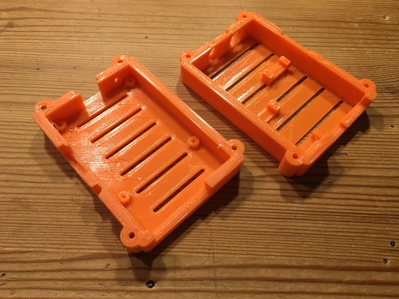
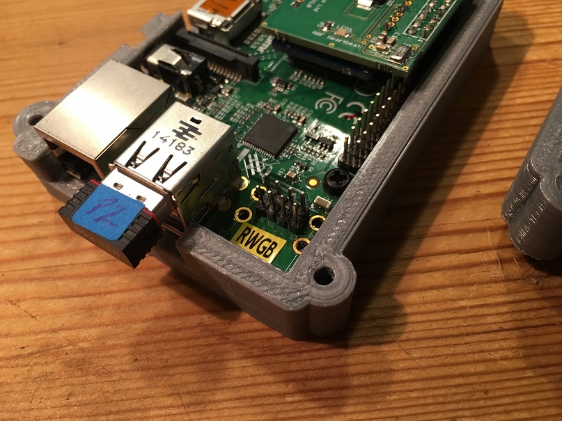
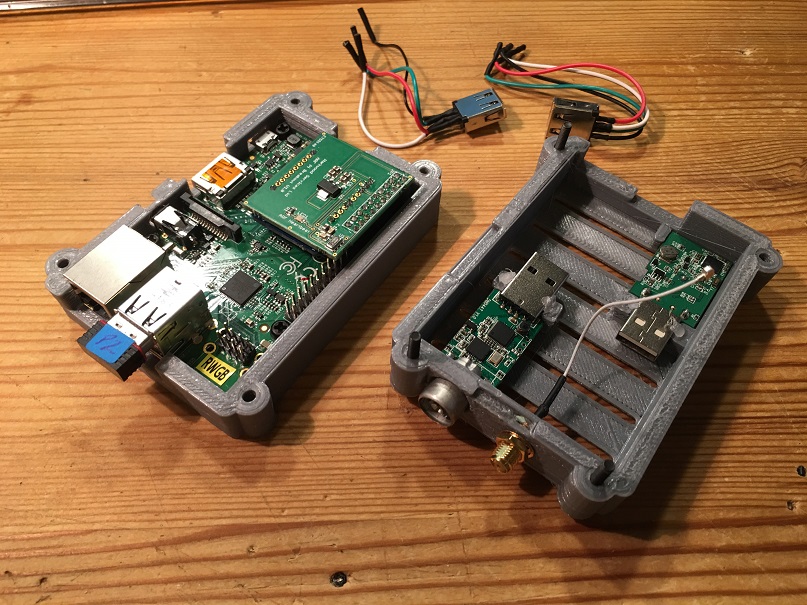
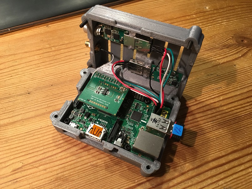
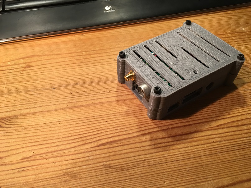


I did notice the GPS was rather less sensitive in there with the ARF powered up, but being next to the ARF is probably a GPS module's equivalent of sticking your head in a speaker stack at a Motorhead concert.

The OpenSCAD source and the STLs are up on GitHub under the Creative Commons license, so you can do what you want with them.

The case needs a bit more work - the tapered capture in the bolt holes is a bit abrupt, so currently difficult to screw the halves together tightly.

So, if you needed another reason to get yourself a 3D printer for Christmas, there you go!


5
General Discussion / Re: Pi Zero and PilotAware
« on: December 02, 2015, 10:23:20 pm »
Could be useful for a transmit-only P3I "DroneAware" though  ;)

Well, I guess you could use one for that, but it would involve duplicating a lot of stuff that the flight controller already does - a while back I extended the 8-bit MultiWii controller code to do pretty much that, sending telemetry from the controller - GPS, baro, as well as system metrics - out over an XRF (the ARFs smaller sibling) - the project rejoicing in the name 'TelemetWii', as an homage to Elmer Fudd.

The reason we need the Pi in the mix as opposed to a simple microcontroller is to do the heavy-lifting of doing the SDR voodoo to get ADS-B traffic data.  That being said, at £4 a pop the Pi Zero is a lot cheaper than most of the 32-bit microcontrollers now being used on flight control boards....

6
General Discussion / Re: Pi Zero and PilotAware
« on: December 02, 2015, 05:34:33 pm »

Exactly - the Pi Zero (at least the ones I have) boots normally with the latest 2015-11-21 Jessie images (https://www.raspberrypi.org/downloads/raspbian/)

Very neat little units, will be great for embedded IoT projects, but as has been noted not the ideal platform for a PAW with USB GPS, DTV and Wifi modules.

7
If you buy a £12 USB GPS dongle for the PAW, you don't need the iPad app, and hence don't need a new iPad.

http://www.ebay.co.uk/itm/USB-GPS-Receiver-VK-172-Ublox7-Fast-10Hz-GPS-Glonass-RasPi-Win-7-8-CE-Linux-/252080341676?hash=item3ab128c2ac:g:foMAAOSwd0BV6Y6t

8
General Discussion / Re: Barometric Sensor
« on: October 29, 2015, 09:00:41 pm »
Yes, I championed the Adafruit baro a while ago but I have started seeing odd QNH values from it with 3 out of 4 PAWs I have fitted them too  :( :(

It's odd as the 4th one is fine, so it's hard to believe there in an inherent problem with using it but 3 / 4 bad is not good.

Keep an eye on the QNH values reported when the whole system is running especially over time. My bad ones tend to drift upwards over time, the 4th is steady at a comparable METAR QNH !

Good if yours is giving sensible results!

Does the Adafruit breakout have pull-up resistors on the I2C bus? - as noted elsewhere, the Pi already has I2C pull-ups, and if the breakout adds them in parallel this can reduce the pull-up resistance to the point that I2C becomes unreliable - I've seen this when using other break-outs, including Adafruit ones, with the Pi.

With an Arduino-type setup that these breakouts are intended for, the intrinsic pullups on the microcontroller can be disabled, but as far as I'm aware you can't do this with the Pi (I believe there is a second I2C bus available without them, but this isn't available on the main GPIO connector...)


9
General Discussion / Re: Regulator board & ARF Board
« on: October 08, 2015, 09:52:51 pm »

Thank you for your reply.  I have no experience in this area at all. If I have a prototype can it be scanned into a CAD program for printing? This would make it easy to reproduce.

I'm getting out of my depth now

No problem - if you post up some pictures of the completed prototype case - sounds like you're building it by hand - I'll ask you for dimensions of specific features and see if I can recreate it in OpenSCAD.  There are 3D scanners which can digitise existing objects, but a) I don't think they work well with objects that have significant internal voids and b) I don't have one.

Probably scope for a thread on enclosures as I think we've hijacked the Regulator and ARF topic enough now!

10
General Discussion / Re: Regulator board & ARF Board
« on: October 08, 2015, 08:33:23 pm »
Can a 3D printer work to produce a case on a small scale. A large company would want a run on many thousands to even be interested.

Absolutely - head over to Thingiverse http://www.thingiverse.com/ and search for 'Raspberry Pi' - loads of case designs of all types.

Designing one without access to a printer, or experience of using one, might be time consuming as there is a learning curve as to what structures are feasible to 3D print (you can't print on thin air using the widely used Fused Filament Fabrication style of printer...at least, not for very far...although more sophisticated printers can use support materials which can be dissolved) and then you get into what can often be a black art of finding a combination of materials and temperatures which will stick to the print bed when you want it to, not stick to the print bed when you don't want it to, and not warp as different parts of the print cool.  Finally, some materials don't react well to being placed in direct strong sunlight.

There are many tools you could use for the design - some folk use Google Sketchup - http://www.sketchup.com/ - but coming from a software development background I prefer OpenSCAD - http://www.openscad.org/ - which uses a declarative language with a syntax akin to C to define solids, and more lately Solid Python, a Python library which compiles designs into OpenSCAD. 

Regardless of what you use, if you can end up with an STL definition of your design send it over and I'll have a go at printing it for you.


11
General Discussion / Re: Regulator board & ARF Board
« on: October 08, 2015, 05:19:11 pm »

If you go...

My Shield
ARF
GPS

Then things are tight space wise and you will sandwich the GPS between the Pi CPU and ARF

If you mean...

GPS
My Shield
ARF

That would be better, but you need a taller case...

The 3.3v regulator I use is rated for 950ma constant with a max of 1.3A, so should be OK.

Certainly the latter! - to give the GPS as clear a view of sky as possible if for no other reason.  Regarding enclosure, as per previous will be custom 3D printed.  Having all of the components fixed in a single enclosure preferable for the aerobatic brigade as the potential for bits falling out and getting jammed where they shouldn't.

12
General Discussion / Re: Regulator board & ARF Board
« on: October 08, 2015, 04:27:20 pm »
As I was short delivered the 2x10 headers, next window for purchase will be tomorrow once the balance of them arrive - the ARF's will be here by then too.  Then it will be early next week when some more PCBs arrive.

Would it be possible to order a couple of the basic boards without the headers soldered to them? - I'd like to use the longer pin style of headers with a view to stacking an I2C GPS prototype HAT on top of the ARF regulator board.

Yes, in the additional notes bit in the shopping cart put that you don't want the 2x10 headers on.  Then as a backup when it sends you the confirmation send it to me to ensure I don't miss the note!  More boards are expected early next week.

I would not put anything between the ARF and Pi CPU - it's tight in there and warm with lots of RF plus it's hard to get the connector out.

Note do not add any pull up resistors for the I2C bus, the Pi has them already on board.

Thanks - will order now with the note.  The plan is to stack the I2C GPS HAT on top of the ARF board, hence putting the long-pin header on the ARF board.  Interesting point about cooling - once I have the boards set up will whip together a suitable 3D printed enclosure with additional venting both for a Pi with your board and also with the GPS board on top and post up the .py/.scad/.stl files.


13
General Discussion / Re: Regulator board & ARF Board
« on: October 08, 2015, 03:03:32 pm »
As I was short delivered the 2x10 headers, next window for purchase will be tomorrow once the balance of them arrive - the ARF's will be here by then too.  Then it will be early next week when some more PCBs arrive.

Would it be possible to order a couple of the basic boards without the headers soldered to them? - I'd like to use the longer pin style of headers with a view to stacking an I2C GPS prototype HAT on top of the ARF regulator board.

14
General Discussion / Re: USB-GPS Working in PilotAware
« on: October 01, 2015, 11:13:46 pm »

I cannot find a GPS that uses SPI or I2C that has support for the RPi today.


Apologies if this is old news - just registered, catching up with developments - but you might want to look at one of these:

http://www.ebay.co.uk/sch/i.html?_from=R40&_trksid=p2050601.m570.l1313.TR12.TRC2.A0.H0.XI2C+GPS.TRS0&_nkw=I2C+GPS&_sacat=0

in combination with one of these:

http://www.ebay.co.uk/itm/Ublox-NEO-6M-GPS-Module-Aircraft-Flight-Controller-APM2-for-Arduino-/252100899673?hash=item3ab2627359

The former is essentially a minimal Arduino which reads parses NMEA or UBLOX protocol from the GPS and behaves as an I2C slave, responding with positioning data packets to an I2C master.  The drone brigade have been using these for a while to remove NMEA parsing duties from the flight controllers, but now that high speed 32 bit ARM controllers are becoming the norm as opposed to wheezing 8 bit Atmega systems the GPS parsing is now generally done by the flight controller.  The I2C-GPS breakouts and the UBlox GPS modules are cheap as chips from China, if you can't wait then let me know as I've got a few spare units kicking around and I'll send a pair over to you.

Will probably need some logic-level shifting for the Pi, but that's easily done.

Pages: [1]